
Motor Driven Piston Chemical Dosing Pump
A process pump specifically designed for low flow, high pressure, and precise dosing application.
Mechanical Piston Dosing Pump
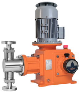
Flowrate: 1 – 3800 l/h (Standard Product) / custom order up to 20,000 l/h for a single pump head.
Pressure: Up to 500 bar.
Common Applications: High Pressure / High Viscosity / High Temperature / Precise Dosing
Upgrade to SMART digital piston pump
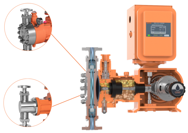
WRS latest SMART digital dosing pump technology is also implementable to our Piston & Hydraulic diaphragm dosing pump series. Instead of using the traditional Variable Speed Drive method, this allows more controls capability and high accuracy dosing, thanks the development of the Servo Motor and BLDC Motor.
To see the complete SMART digital version, please see the SMART Series Piston Pump’s tab below.
Optional for interchangeable induction motor:



WRS pumps are designed with various configurations, offering different type of solutions to meet all of our client’s requirements. From pump head design, motor types to control variants.
Options:
- Variable Frequency Motor
- Explosion Proof Motor
- Variable Frequency + Explosion Proof Motor
(Standard on stock motor: ExdIIBT4, other options are available upon request.) - BLDC / Servo Motor (SMART Series Piston Pump)
*Note: Variable Frequency motor is not required for digital control. Digital control will paired with Servo Motor / BLDC Motor to achieve flow rate control in a much better accuracy.
Suction & Discharge Connection Method Options:
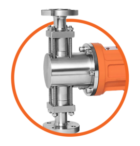
Able to match user’s requirements or factory’s standard connection. Either flange, threaded according to your local standards.
Optional upgrade of pump head/cooling.
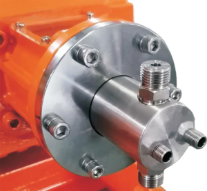
Specially designed for fluid required stable operating temperature. Applicable to both Piston & Hydraulic Diaphragm Dosing Pump.
Multiple Pump Head Configuration
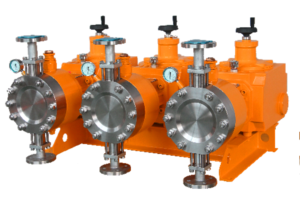
Optional to manufacture multiple pump heads for special application such as: high flow or mixing application. Pump can be run with single motor. Applicable to both Piston & Hydraulic Diaphragm Dosing Pump as they share the same pump body.
- First two blank boxes: For multiple pump head use. Empty if it is only single pump head.
- Third blank box (before pump size): For digital control use. Empty if it is a manual control pump.
- Trailing “-XXX”: For any non standard / custom make use (Factory to provide). Empty if it is according to standard design as shown in this brochure.
| Example | Category | Description |
|---|---|---|
| – | Pump Head Quantity | None – Single Pump Head 2 – Twin Head 3 – Triple Head X – Custom Make *2 |
| – | Digital or Manual Control | None – Manual Control E – With Digital Control |
| PS | Pump Body | PS PM PL PD P* – Custom Make Body Size *2 |
| – | Digital Control Method | P – Plus Series L – Lite Series None – No Digital Control |
| 020 | Piston Size | 006 – 200 |
| S | Pump Head Material | S – SS316L C – SS304 D – Duplex 2205 H – Hastelloy C X – Custom Make *2 |
| 0 | Pump Head Heating/Cooling | 0 – None 1 – Liquid/Stem Heating/Cooling 2 – Electric Heating X – Custom Make *2 |
| P | Piston Surface Material | P – Ceramic C – Tungsten Carbide X – Custom Make *2 |
| 0 | Valve Spring | 0 – No Spring 1 – Inlet Spring 2 – Outlet Spring 3 – Both Inlet & Outlet with Spring |
| 1 | Packing Seal | 1 – PTFE Packing X – Custom Make *2 |
| S | Connection Method | S – Bevel End Welding Tube F – Flanged (user to provide flange standard) P – Inner Thread (user to provide thread standard) X – Custom Make *2 |
| 1 | Power Required | 1 – 380V 50HZ 3Phase 2 – 220V 50Hz 1Phase X – Custom Make *2 |
| 1 | Motor Type | 0 – No Motor 1 – IEC Motor 2 – Variable Frequency Motor 3 – Explosion Proof Motor (Exd IIB T4) 4 – Variable Frequency and Explosion Proof Motor (Exd IIB T4) X – Custom Make *2 |
| XXX | Custom Make Code | For factory use only. Reserved for custom make selections. |
*Notes:
1) Identification code are for identifying the pump not for complete selection. If there are any question on selection, please contact with us or our representative.
2) All custom make selection shall make confirmation with factory.
PISTON PUMP TECHNICAL PARAMETERS
All data are tested in an indoor environment, with clean water at ambient temperature. Pumps are connected to a 50Hz power supply.
PS
| Model | Max. Flowrate (Lph) |
Max. Back Pressure (Bar) | Piston Diameter (mm) |
SPM | Stroke Length (mm) |
Default Connection Method | |
|---|---|---|---|---|---|---|---|
| 0.25 KW | 0.37 KW | ||||||
| 006* | 1 | 300 | 400 | 6 | 96 | 10 | DN6 Bevel End Welding Tube |
| 006* | 2 | 230 | 350 | 6 | 96 | 20 | |
| 008 | 5 | 210 | 320 | 8 | 96 | 20 | |
| 010 | 8 | 130 | 200 | 10 | 96 | 20 | |
| 012 | 12 | 100 | 150 | 12 | 96 | 20 | |
| 016 | 20 | 50 | 80 | 16 | 96 | 20 | DN10 Bevel End Welding Tube |
| 020 | 35 | 33 | 50 | 20 | 96 | 20 | |
| 025 | 55 | 21 | 32 | 25 | 96 | 20 | |
| 032 | 85 | 13 | 20 | 32 | 96 | 20 | |
| 035 | 100 | 12 | 18 | 35 | 96 | 20 | |
| 038 | 125 | 10 | 16 | 38 | 96 | 20 | DN15 Bevel End Welding Tube |
| 042 | 160 | 7 | 10 | 42 | 96 | 20 | |
| 042 | 240 | 3 | 5 | 42 | 144 | 20 | |
*Notes: Please contact with our engineers or local sales representative when choosing these models.
PM
| Model | Max. Flowrate (Lph) |
Max. Back Pressure (Bar) | Piston Diameter (mm) |
SPM | Stroke Length (mm) |
Default Connection Method | |
|---|---|---|---|---|---|---|---|
| 0.55 KW | 0.75 KW | ||||||
| 008 | 6 | 400 | 500 | 8 | 96 | 25 | DN6 Bevel End Welding Tube |
| 010 | 10 | 300 | 400 | 10 | 96 | 25 | |
| 012 | 15 | 220 | 300 | 12 | 96 | 25 | |
| 016 | 25 | 180 | 180 | 16 | 96 | 25 | |
| 020 | 42 | 70 | 100 | 20 | 96 | 25 | |
| 025 | 65 | 50 | 70 | 25 | 96 | 25 | DN10 Bevel End Welding Tube |
| 032 | 110 | 30 | 40 | 32 | 96 | 25 | |
| 038 | 160 | 20 | 28 | 38 | 96 | 25 | |
| 045 | 220 | 15 | 20 | 45 | 96 | 25 | DN15 Bevel End Welding Tube |
| 050 | 250 | 12 | 16 | 50 | 96 | 25 | |
| 055 | 340 | 8 | 12 | 55 | 96 | 25 | DN25 Flange |
| 060 | 400 | 7 | 10 | 60 | 96 | 25 | |
| 070 | 550 | 6 | 8 | 70 | 96 | 25 | |
| 065 | 700 | 4 | 6 | 65 | 144 | 25 | |
| 070 | 800 | 3 | 5 | 70 | 144 | 25 | |
PL
| Model | Max. Flowrate (Lph) |
Max. Back Pressure (Bar) | Piston Diameter (mm) |
SPM | Stroke Length (mm) |
Default Connection Method | |
|---|---|---|---|---|---|---|---|
| 1.1 KW | 1.5 KW | ||||||
| 012 | 16 | 400 | 500 | 12 | 96 | 30 | DN10 Bevel End Welding Tube |
| 016 | 32 | 220 | 300 | 16 | 96 | 30 | |
| 020 | 50 | 130 | 180 | 20 | 96 | 30 | |
| 025 | 80 | 70 | 100 | 25 | 96 | 30 | |
| 032 | 130 | 60 | 80 | 32 | 96 | 30 | DN15 Bevel End Welding Tube |
| 038 | 200 | 35 | 50 | 38 | 96 | 30 | |
| 045 | 260 | 25 | 35 | 45 | 96 | 30 | |
| 050 | 320 | 22 | 30 | 50 | 96 | 30 | |
| 060 | 480 | 16 | 22 | 60 | 96 | 30 | DN25 Flange |
| 070 | 650 | 12 | 16 | 70 | 96 | 30 | |
| 080 | 850 | 9 | 12 | 80 | 96 | 30 | DN40 Flange |
| 090 | 1050 | 6 | 9 | 90 | 96 | 30 | |
| 080 | 1300 | 6 | 8 | 80 | 144 | 30 | |
| 090 | 1600 | 4 | 6 | 90 | 144 | 30 | |
PD
| Model | Max. Flowrate (Lph) |
Max. Back Pressure (Bar) | Piston Diameter (mm) |
SPM | Stroke Length (mm) |
Default Connection Method | ||
|---|---|---|---|---|---|---|---|---|
| 2.2 KW | 3.0 KW | 4.0 KW | ||||||
| 012 | 25 | 400 | 500 | 500 | 12 | 96 | 50 | DN10 Bevel End Welding Tube |
| 016 | 50 | 300 | 400 | 500 | 16 | 96 | 50 | |
| 020 | 85 | 180 | 250 | 350 | 20 | 96 | 50 | DN15 Bevel End Welding Tube |
| 025 | 130 | 120 | 160 | 220 | 25 | 96 | 50 | |
| 032 | 220 | 65 | 90 | 130 | 32 | 96 | 50 | |
| 038 | 320 | 50 | 68 | 90 | 38 | 96 | 50 | |
| 045 | 450 | 35 | 48 | 70 | 45 | 96 | 50 | DN25 Flange |
| 050 | 550 | 30 | 40 | 56 | 50 | 96 | 50 | |
| 055 | 680 | 25 | 34 | 47 | 55 | 96 | 50 | |
| 060 | 800 | 20 | 28 | 40 | 60 | 96 | 50 | |
| 070 | 1100 | 15 | 20 | 28 | 70 | 96 | 50 | DN40 Flange |
| 075 | 1250 | 13 | 18 | 25 | 75 | 96 | 50 | |
| 085 | 1600 | 10 | 14 | 20 | 85 | 96 | 50 | |
| 095 | 2000 | 8 | 11 | 15 | 95 | 96 | 50 | |
| 105 | 2500 | 6 | 8 | 10 | 105 | 96 | 50 | |
| 095 | 3000 | 5 | 7 | 9 | 95 | 144 | 50 | DN50 Flange |
| 105 | 3800 | 4 | 5 | 7 | 105 | 144 | 50 | |
DIGITAL CONTROL PISTON / HYDRAULIC DIAPHRAGM PUMP
*Above images are for illustration purposes only. Actual unit may be different subject to pump size, pump type, explosion proof requirements etc.
| PLUS | LITE | ||
|---|---|---|---|
| GENERAL | |||
| Display Type | Touch screen HMI | √ | – |
| Back light LCD | – | √ | |
| Operating Method | Touch screen keypad | √ | – |
| Soft button (Start/stop, Up, Down) | – | √ | |
| Information Display | Current flowrate (LPH) | √ | √ |
| Accumulated flowrate (L). Resetable. | √ | √ | |
| Current pressure/level value (Bar / m) | √ | – | |
| Current pump status / warnings | √ | – | |
| Password Protection | To prevent unauthorized personal to make changes | √ | – |
| CONTROL | |||
| Manual | User may set the flow rate in litres/hour via the control panel on the pump itself (P series = touch screen, L series = soft keys) and the pump automatically adjust to dose user’s set flow rate. | √ | √ |
| Signal Control | Current analog (4-20-mA). In this operating mode, the pump doses according to an external analog signal, and the flow rate being pumped is proportional to the signal input value (mA), where 4mA = 0% of the design flow rate and 20mA = 100% of the design flow rate. | √ | √ |
| Current analog reversed (20-4-mA). In this operating mode, the pump doses according to an external analog signal, and the flow rate being pumped is proportional to the signal input value (mA), where 4mA = 100% of the design flow rate and 20mA = 0% of the design flow rate. | √ | √ | |
| Current analog linear mode (mA). In this operating mode, user set 2 values, P1 & P2 (LPH). The pump doses according to an external analog signal, and the flow rate being pumped is proportional to the signal input value (mA), where 4mA = P1 of the design flow rate and 20mA = P2. | √ | √ | |
| Pulse frequency control. In this mode, user set the max. pulse frequency value (Max. 600). The pump can be controlled by receiving a pulse frequency signal from an external source. The pump doses at 100% at max pulse value and 0% at 0 pulse signal. | – | √ | |
| Remote On/Off | Dry contact (normally open). By connecting two wires, the pump can be remotely turn on/off via potential-free contacts. Typically used in programmable logic controllers (PLCs) or a level float switch. | √ | √ |
| Communication | RS485 RTU Modbus. Pumps can be remotely controlled using an Intelligent Pump Controller (IPC) by connecting to a dedicated RS485 terminal strip using a cable from the remote connection device. Common parameters include device address and baud rate. | √ | √ |
| Batch | Doses in batches based on the dosing value (in liters) set in the dosing mode. Can be activated either by receiving a pulse signal or on/off from the pump. If activating via pulse signal, one batch is dosed each time the pump receives an pulse signal. | √ | √ |
| Batch + Timer | Doses in batches based on the dosing value (in liters) at specified time. Instead of activated by pulse or pump on/off, it is activated by the timer. Up to three time points can be set in one day. | √ | – |
| Batch Deviation | Fine tuning batch dosing accuracy. In actual application, there are many factors will affect the dosing accuracy. Users can fine tune the error by entering the differential value. | √ | √ |
| Cycle | Cycle mode runs based on the “Run Time” and “Stop Time” set by the user. Example: “Run Time” is set to 20 minutes, “Stop Time” is set to 30 minutes. When the pump starts, the pump will be run for 20 minutes, stop for 30 minutes, run for 20 minutes, stop for 30 minutes… and repeat this operation. | √ | – |
| Timer | The timer mode runs based on timer. User to set “Start Time” and “Stop Time” in terms of HH:MM:SS. There are 3 sets of timer able to adjust per day. The timer will be repeat everyday. | √ | – |
| OTHER FEATURES | |||
| Low Level Alarm | Low liquid level alarm. Receive low level signal from an external dry contact. | √ | – |
| Pressure / Level Alarm | Alarm/stop the pump according to the level/pressure set point set by the user. This pump can alarm/stop operation according to the signal from the level sensor. Choose one of the two. | √ | – |
| Calibration Function | It has a built-in program to automatically adjust the flow rate. When the installation is complete, the user only needs to enter the actual flow rate. | √ | √ |
| Diaphragm Rupture Sensor | Optional double diaphragm rupture alarm system for safety. (For Hydraulic Diaphragm Pump Only) | √ | √ |
MATERIAL TABLE
| Material Code | Piston Pump |
|---|---|
| Pump Fluid End: | |
| Pump Head Material | SS316L |
| Piston | Full Ceramic (Low Flow) Or SS Coated Ceramic Surface |
| Inlet & Outlet Valve | Body: SS316L |
| Seat: SS316L | |
| Ball: Ceramic | |
| Seal | PTFE |
| Others | |
| Pump Body | Cast Iron |
*Notes: 1) Above material table refers to the standard models. Customizable material is available upon request.
PISTON PUMP DIMENSION (mm)
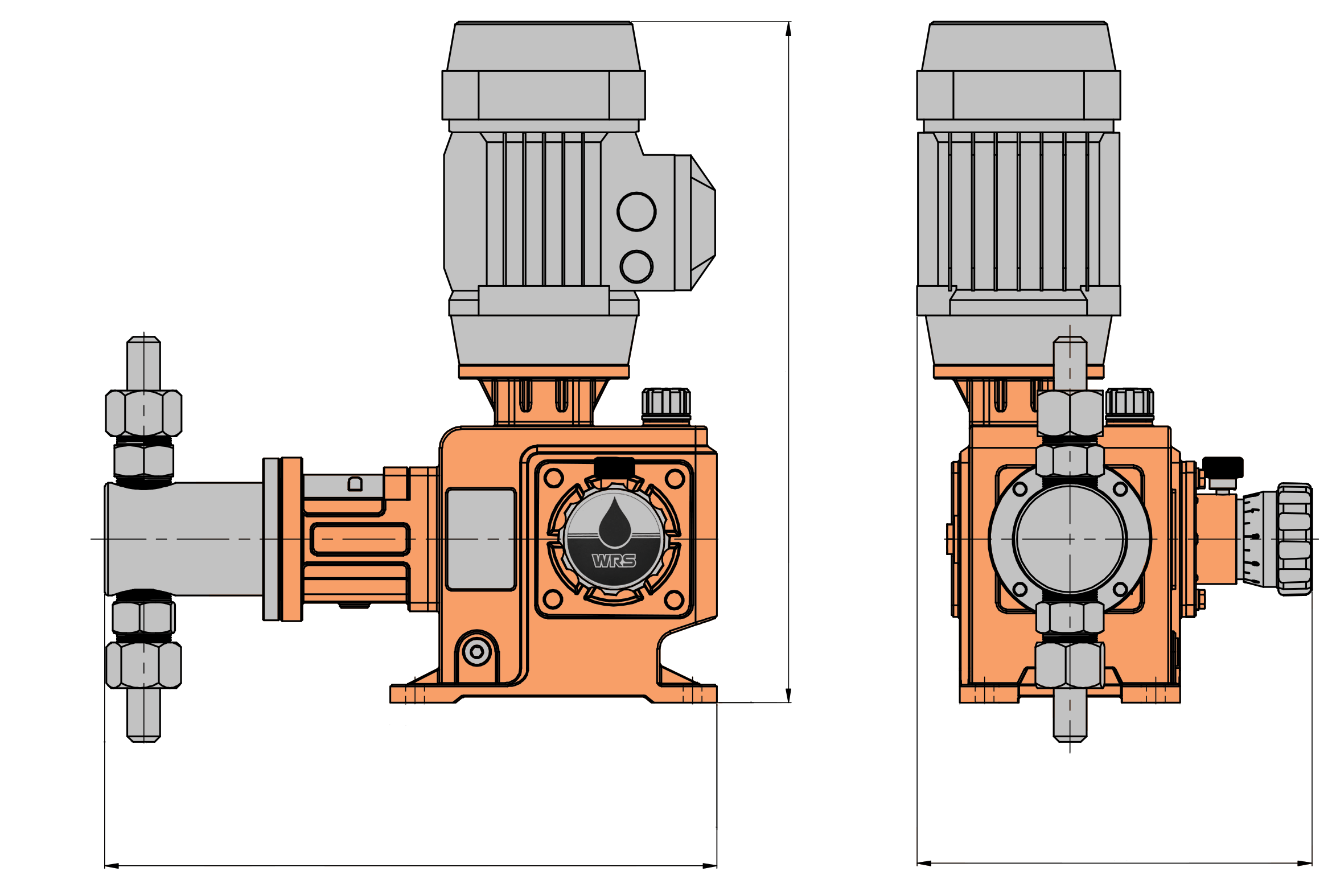
| L | W | H | |
|---|---|---|---|
| PS | 383 | 242 | 417 |
| PM | 492 | 333 | 480 |
| PL | 576 | 369 | 574 |
| PD | 770 | 506 | 720 |
Piston Dosing Pump Head Structure
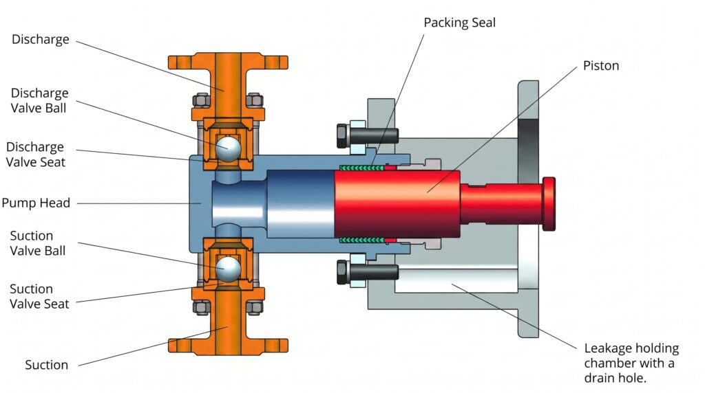
WRS Motor Driven Piston Pump Head Diagram
Piston Dosing Pumps: Precision Chemical Injection for High-Pressure Applications
A piston dosing pump is a heavy-duty, positive displacement metering pump engineered to deliver highly accurate volumes of liquid chemicals. Designed for reliability in demanding environments, these pumps are the go-to solution when your process requires precise chemical injection against high system pressures.
How It Works
A piston dosing pump operates using a simple but highly effective reciprocating mechanism.
-
Suction Stroke: As the motor drives the piston backward, it creates a vacuum in the pump head, drawing the chemical in through the inlet valve.
-
Discharge Stroke: As the piston moves forward, it pressurizes the chamber, pushing a precise, repeatable volume of the chemical out through the discharge valve and into your process line.
Common Industries & Applications
Because of their rugged design, piston metering pumps are utilized across a wide variety of heavy-duty sectors:
-
Water and Wastewater Treatment: Dosing coagulants, flocculants, and pH adjusters.
-
Oil and Gas: Injecting corrosion inhibitors, methanol, and other treatment chemicals into high-pressure pipelines.
-
Chemical Processing: Precise blending and transferring of industrial solvents and reagents.
-
Agriculture: Delivering exact volumes of liquid fertilizers and nutrients into irrigation systems.
Why Choose a Piston Pump?
When comparing chemical injection pumps, piston designs offer distinct advantages over standard mechanical diaphragm pumps:
-
Superior Pressure Capabilities: Piston pumps excel in applications requiring discharge against extreme system pressures where other pump types would fail.
-
Exceptional Accuracy: The rigid displacement of a solid piston provides a highly linear flow rate, ensuring near-perfect repeatability for strict dosing requirements.
-
Durability: Built for continuous, heavy-duty operation, making them a staple in heavy industrial plants.
Explore the complete range of WRS piston dosing pump models and capacities below to find the exact configuration for your fluid handling needs.