
Solenoid Driven Diaphragm Chemical Dosing Pump Series
EML MODELS
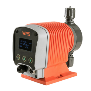
Flowrate: 1 – 20 LPH
Pressure: 10 – 1 Bar
Material: PVC / PVDF / SS304 / SS316
Flowrate Control: Pulse / 4-20mA Signal Control
MLS SERIES
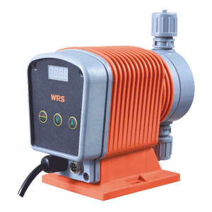
Flowrate: 1 – 20 LPH
Pressure: 10 – 1 Bar
Material: PVC / PVDF / SS304 / SS316
Flowrate Control: Pulse / 4-20mA Signal Control
ML SERIES

Flowrate: 1 – 20 LPH
Pressure: 10 – 1 Bar
Material: PVC / PVDF / SS304 / SS316
Flowrate Control: Manual Only
| EML | MLS | ML | ||
|---|---|---|---|---|
| GENERAL | ||||
| Pump Display | 48 x 30mm Back Light LCD Screen | √ | – | – |
| 4 Digit 7-segment LED Display | – | √ | √ | |
| Home Screen Display Information | Flowrate Percentage (%) | √ | √ | √ |
| Current Dosing Flowrate Display (LPH) | √ | – | – | |
| Accumulated Dosed Volume (L) | √ | – | – | |
| Operating Method | 3 Soft Buttons (Start/Stop; Up; Down) | √ | √ | √ |
| Calibration Function | Enter the actual flowrate to get the true performance range of the pump | √ | – | – |
| Stroke Speed Adjustment | Every pump comes with Stroke Speed adjustment feature. Allowing user to fine tune discharge flowrate. | √ | √ | √ |
| Included Accessories* | Injection valve, foot valve, bleed valve, PE Hose, Ceramic Weight. *(Not available for Stainless Steel Pump Head) | √ | √ | √ |
| Signal Cable | Included as accessories for EML & MLS for signal connection. | √ | √ | – |
| CONTROLS | ||||
| Manual | The dosing flowrate can be set on the pump through flowrate percentage adjustment. The setting range is 0-100% of the design flowrate. 100% is the maximum flowrate of the pump, and 0% is zero flowrate. | √ | √ | √ |
| Signal | Current analog control (4-20-mA). In this operating mode, the pump doses according to an external analog signal, and the flow rate being pumped is proportional to the signal input value (mA), where 4mA = 0% of the design flow rate and 20mA = 100% of the design flow rate. | √ | √ | – |
| Pulse signal multiply (1:N). The pump can be controlled by receiving a pulse signal from an external source. The pump performs “n” strokes for each incoming pulse. Where “n” can be set between 1 and 255. | √ | √ | – | |
| Pulse signal divide (N:1). The pump can be controlled by receiving a pulse signal from an external source. The pump performs “1” strokes for “n” incoming pulse. Where “n” can be set between 1 and 255. | √ | √ | – | |
| Remote On/Off | Dry contact (normally open). By connecting two wires, the pump can be remotely turn on/off via potential-free contacts. Typically used in programmable logic controllers (PLCs) or a level float switch. | √ | √ | – |
| Communication | RS485 RTU Modbus. Pumps can be remotely controlled using an Intelligent Pump Controller (IPC) by connecting to a dedicated RS485 terminal strip using a cable from the remote connection device. Common parameters include device address, baud rate and start/data/stop bits. | √ | – | – |
| Example | EML | 0020 | P | R | 1 | E |
|---|---|---|---|---|---|---|
| Category | Model | Flowrate | Fluid-End Material | Connection Method | Power Required | Plug Type |
| Category | Description |
|---|---|
| Model | EML – SMART model with 4-20mA / pulse signal / RS485 RTU control. MLS – Simple model with 4-20mA / pulse signal control. ML – Basic model with manual control. |
| Flowrate | 001 … 020 – See table in next page. |
| Fluid-End Material | P – PVC S – SS316L F – PVDF X – Customized |
| Connection Method | R – Hose Connection (5*8mm ID*OD) X – Customized |
| Power Required | 1 – 220V / 50Hz or 60Hz / 1Phase 2 – 110V / 50Hz or 60Hz / 1Phase |
| Plug Type | A – America I – Australia / New Zealand C – China N – No Plug E – Europe G – United Kingdom X – Customized |
*Notes: Identification code are for identifying the pump not for complete selection. If there are any question on selection, please contact with us or our representative.
| 001 | 002 | 004 | 005 | 008 | 010 | 012 | 015 | 020 | |
|---|---|---|---|---|---|---|---|---|---|
| Max. Discharge Flowrate (50Hz) Lph | 1 | 2 | 4 | 5 | 8 | 10 | 12 | 15 | 20 |
| Max. Discharge Pressure *1 Bar | 10 | 10 | 8 | 5 | 4 | 3 | 3 | 2 | 1.5 |
| Stroke Speed *2 spm | 80 | 140 | 180 | 140 | 170 | 130 | 150 | 160 | 180 |
| Stroke Length mm | 1.5 | 2 | |||||||
| Diaphragm Diameter mm | 34 | 41 | 52 | ||||||
| Maximum Suction Lift mm | 1.5 | ||||||||
| Max. Allowable Viscosity cps | 200 | ||||||||
| Max. Particle Size | Particle Diameter < 0.2mm, Solid Content < 20% | ||||||||
| Maximum Suction Pressure Bar | 2 | ||||||||
| Minimum Differential Pressure Bar | 1 | ||||||||
| Standard Material Allowable Fluid Temperature (No Freezing Allowed) °C | PVC: +5 to +40 PVDF / SS316L: -10 to +55 |
||||||||
| Ambient Temperature °C | Operating: 0 to +40, Storage: -10 to +50 | ||||||||
| Steady State Accuracy % | 1 | ||||||||
| Standard Suction & Discharge Connection | Tube Compression Fitting (ID*OD: 5*8mm) | ||||||||
| Power Required | Default: 220V / 50Hz or 60Hz / 1Phase Optional: 110V / 50 or 60Hz / 1Phase |
||||||||
| Max. Current Amp | 0.1 | ||||||||
| Average Power Consumption Watt | 28 | ||||||||
| Ingress Protection IP | 65 | ||||||||
| Signal Cable | Included for EML & MLS Models ONLY | ||||||||
*Data are tested based on water at 20°C, fully primed and at maximum back pressure. Actual flowrate may differ in actual setup, depending on your system back pressure, pumping fluid and piping design.
MATERIAL TABLE
| Material Code | P | F | S |
|---|---|---|---|
| Pump Fluid End: | |||
| Pump Head Material | PVC | PVDF | SS316L |
| Diaphragm | PTFE Composite | PTFE Composite | PTFE Composite |
| Inlet & Outlet Valve | Body: PVC | Body: PVDF | Body: SS316L |
| Seat: PTFE | Seat: PTFE | Seat: SS316L | |
| Ball: Ceramic | Ball: Ceramic | Ball: Ceramic | |
| Seal | FKM | FKM | PTFE |
| Standard Accessories (Inclusive in box) | |||
| Injection Valve, Foot Valve, Bleed Valve | Body: PVC | Body: PVDF | No accessories included for Stainless Steel pump head. |
| Seat: PTFE | Seat: PTFE | ||
| Ball: Ceramic | Ball: Ceramic | ||
| Seal | FKM | FKM | |
| Spring | SS316L / Hastelloy | SS316L / Hastelloy | |
| Stabilizing Weight | Ceramic | Ceramic | |
| Flexible Tube | PE | PE | |
| Others | |||
| Pump Body | Reinforced Nylon | ||
PACKING DIMENSION & WEIGHT
| Pump Head Material | PVC | PVDF | SS316L |
|---|---|---|---|
| Net Weight | 3.5 | 3.5 | 4.5 |
| Gross Weight | 4.5 | 4.5 | 5.5 |
| Single Box Packing Dimension (1 set) | 270 x 270 x 170 mm | ||
What is a Solenoid Driven Dosing Pump?
A dosing pump, also commonly known as metering pump or chemical injection pump. It is categorized under positive displacement pump family. The main purpose of a dosing pump is to accurately dose chemical into a system. There are various type of dosing pump such as piston, peristaltic, diaphragm and hydraulic diaphragm. EML, MLS & ML dosing pump is a microprocessor-controlled solenoid diaphragm type dosing pump.
How does it work?
Solenoid metering pump is the use of electromagnetic push rod driven diaphragm in the pump head reciprocating movement, causing the pump head chamber volume and pressure changes. Changes in pressure caused by suction valve and discharge valve opening and closing, to achieve quantitative liquid suction and discharge. A magnet moves the solenoid shaft forwards and backwards by switching on and off. This stroke movement is transferred to the diaphragm in the dosing head. Two non-return valves prevent the feed chemical from flowing back during pumping. But that’s not all. The stroke length and stroke rate can be adjusted to alter the capacity of a ProMinent solenoid-driven metering pump.
Common Applications
- Potable water treatment: Metering of disinfectants
- Cooling circuits: Metering of corrosion inhibitors and biocides
- Waste water treatment: Metering of flocculants
- Paper industry: Metering of additives
- Plastics production: Metering of additives
What are the advantages?
Because there is only one moving part, the drive is virtually wear-free. The pump requires no lubricated bearings or shafts; the maintenance and repair costs are therefore very low. The continuous running characteristics are excellent.
How to choose a solenoid pump?
- Specify pump capacity in litres per hour [l/h].
- Specify back pressure in bar.
- Find the intersection of these two values and select the pump type that lies nearest to it.